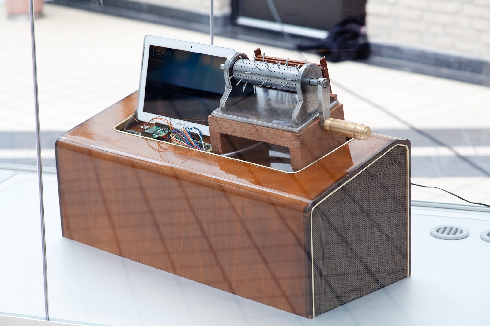

Interpretator 2 "The music box principle"
The interpreter of a musical composition the "Interpretator" is a kinetic installation where images and music meet. "The music box principle" is where the concept is handy, a product that is marketable and suitable for the latest forms of media.
You can use the music box with the right app to connect directly to you Touch Phone, Tablet or Labtop.
A handy reprogrammable music box of about 15 kilo with bleutooth connection, you can program own compositions and play with a snap, record and listen back. The music box principle, a true gadget for the people who know nothing about computers .

Proof of concept
The Music box principle
Pure Data Patches


Arduino Source Code


/*
 * SN74HC165N_shift_reg
 *
 * Program to shift in the bit values from a SN74HC165N 8-bit
 * parallel-in/serial-out shift register.
 *
 * This sketch demonstrates reading in 16 digital states from a
 * pair of daisy-chained SN74HC165N shift registers while using
 * only 4 digital pins on the Arduino.
 *
 * You can daisy-chain these chips by connecting the serial-out
 * (Q7 pin) on one shift register to the serial-in (Ds pin) of
 * the other.
 *
 * Of course you can daisy chain as many as you like while still
 * using only 4 Arduino pins (though you would have to process
 * them 4 at a time into separate unsigned long variables).
 *
*/

/* How many shift register chips are daisy-chained.
*/
#define NUMBER_OF_SHIFT_CHIPS   3

/* Width of data (how many ext lines).
*/
#define DATA_WIDTH   NUMBER_OF_SHIFT_CHIPS * 8

/* Width of pulse to trigger the shift register to read and latch.
*/
#define PULSE_WIDTH_USEC   5

/* Optional delay between shift register reads.
*/
#define POLL_DELAY_MSEC   1

/* You will need to change the "int" to "long" If the
 * NUMBER_OF_SHIFT_CHIPS is higher than 2.
*/
#define BYTES_VAL_T unsigned long

int ploadPin        = 8;  // Connects to Parallel load pin the 165 WIT
int clockEnablePin  = 9;  // Connects to Clock Enable pin the 165 - NIET GEBRUIKT, LIGT AAN AARDE
int dataPin         = 11; // Connects to the Q7 pin the 165 ORANJE
int clockPin        = 12; // Connects to the Clock pin the 165 GEEL

BYTES_VAL_T pinValues;
BYTES_VAL_T oldPinValues;
BYTES_VAL_T pinValues2;
BYTES_VAL_T oldPinValues2;


/* This function is essentially a "shift-in" routine reading the
 * serial Data from the shift register chips and representing
 * the state of those pins in an unsigned integer (or long).
*/


BYTES_VAL_T read_shift_regs(int offset=0)
{
    unsigned long bitVal;
    BYTES_VAL_T bytesVal = 0;

    /* Trigger a parallel Load to latch the state of the data lines,
    */
    digitalWrite(clockEnablePin, HIGH);
    digitalWrite(ploadPin, LOW);
    delayMicroseconds(PULSE_WIDTH_USEC);
    digitalWrite(ploadPin, HIGH);
    digitalWrite(clockEnablePin, LOW);

    /* Loop to read each bit value from the serial out line
     * of the SN74HC165N.
    */

    for(int i = 0; i < DATA_WIDTH-offset; i++)
    {
        bitVal = digitalRead(dataPin);

        // Set the corresponding bit in bytesVal.
        bytesVal |= (bitVal << ((DATA_WIDTH-1-offset) - i));


        // Pulse the Clock (rising edge shifts the next bit).
        digitalWrite(clockPin, HIGH);
        delayMicroseconds(PULSE_WIDTH_USEC);
        digitalWrite(clockPin, LOW);


    }
    return(bytesVal);
}


void display_pin_values_short()
{
    uint16_t xlow = pinValues & 0xffff;
    uint16_t xhigh = (pinValues >> 16);
    uint8_t chip1 = xlow & 0xff;
    uint8_t chip2 = (xlow >> 8);
    uint8_t chip3 = xhigh & 0xff;
    uint8_t chip4 = (xhigh >> 8);
    uint16_t bank_low = pinValues2 & 0xffff;
    uint16_t bank_high = (pinValues2 >> 16);
    uint8_t chip5 = bank_low & 0xff;
    uint8_t chip6 = (bank_low >> 8);

//    Serial.print("/values1 ");
//    Serial.println(pinValues,BIN);
//    Serial.print("/values2 ");
//    Serial.println(pinValues2);
    Serial.print("A ");
    Serial.print(chip1);
    Serial.print(' ');
    Serial.print(chip2);
    Serial.print(' ');
    Serial.print(chip3-128);
    Serial.println('!');
//    Serial.print("/chip1 ");
//    Serial.println(chip1);
//    Serial.print("/chip2 ");
//    Serial.println(chip2);
//    Serial.print("/chip3 ");
//    Serial.println(chip3-128);
//    Serial.println(chip1 * chip2 * (chip3-128));
//    Serial.print("/chip4 ");
//    Serial.println(chip4);
//    Serial.print("/chip5 ");
//    Serial.println(chip5);
//    Serial.print("/chip6 ");
//    Serial.println(chip6);
    delay(10);
}


void setup()
{
    Serial.begin(57600);

    // Initialize our digital pins...

    pinMode(ploadPin, OUTPUT);
    pinMode(clockEnablePin, OUTPUT);
    pinMode(clockPin, OUTPUT);
    pinMode(dataPin, INPUT);

    digitalWrite(clockPin, LOW);
    digitalWrite(ploadPin, HIGH);

    // Read in and display the pin states at startup.
    pinValues = read_shift_regs();
    pinValues2 = read_shift_regs(32);
    display_pin_values_short();
    oldPinValues = pinValues;
    oldPinValues2 = pinValues2;
}

void loop()
{
    // Read the state of all zones.

    pinValues = read_shift_regs();
    pinValues2 = read_shift_regs(32);

    //If there was a chage in state, display which ones changed.
    if(pinValues != oldPinValues || pinValues2 != oldPinValues2)
    {
        display_pin_values_short();
        oldPinValues = pinValues;
        oldPinValues2 = pinValues2;
    }

    delay(POLL_DELAY_MSEC);
}
Special thanks to Corneel Canters and David Lamain
No comments:
Post a Comment